Intuition

Bit manipulation is a technique used in programming to perform operations at the bit level, which can often lead to more efficient and faster algorithms.

When is bit manipulation useful?
Bit manipulation allows us to work directly with the binary representation of numbers, making certain operations more efficient. Common tasks such as setting, clearing, toggling, and checking bits can be performed quickly using bitwise operators.

For example, one of the most common space optimization techniques involves using an unsigned 32-bit integer to represent a set of boolean values, where each bit in the integer corresponds to a different boolean value. This allows us to store and manipulate up to 32 states without using a boolean array or hash set.

Image represents a visual depiction of a binary counter's behavior.  The image shows a sequence of vertical arrows, each labeled at the top with either 'T' (representing True) or 'F' (representing False), and at the bottom with a binary digit (0 or 1) and a corresponding decimal number.  The arrows indicate a downward flow of information.  The decimal numbers (31, 30, 29, ..., 1, 0) decrease sequentially from left to right, representing a countdown.  The binary digits (0 and 1) alternate, with 'T' consistently mapping to '1' and 'F' to '0'.  An ellipsis (...) indicates the omission of intermediate steps in the sequence, implying the counter continues this pattern until it reaches zero.  The gray arrows and numbers suggest a less significant or inactive state compared to the black arrows and numbers, which represent the active counting process.

Bitwise Operators

There are several fundamental bitwise operations, each serving a specific purpose. These are shown below, along with each operation’s truth table:
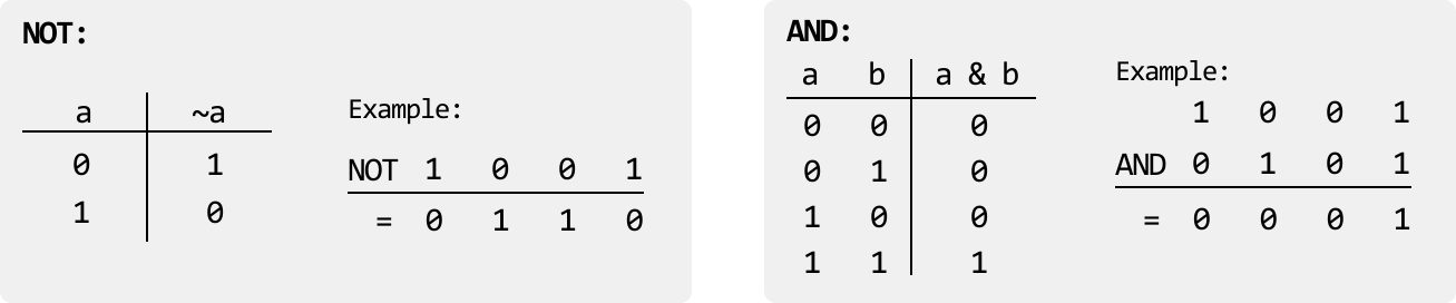
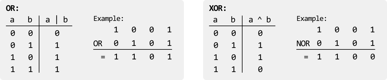
Image represents a visual explanation of Boolean logic gates, specifically the NOT and AND gates.  The left side depicts the NOT gate, showing a truth table with a single input 'a' and an output '~a'.  The table lists input values of 0 and 1 for 'a', resulting in corresponding output values of 1 and 0 for '~a', respectively.  Below the table, an example is provided:  applying the NOT operation to the input '1' yields an output of '0', and applying it to '0' yields '1'. The right side illustrates the AND gate, presenting a truth table with two inputs, 'a' and 'b', and an output 'a & b'.  The table shows all possible combinations of 0 and 1 inputs for 'a' and 'b', with the output 'a & b' being 1 only when both 'a' and 'b' are 1; otherwise, it's 0.  An example calculation is shown below, where '1 AND 0' results in '0'.  Both sections clearly demonstrate the functionality of each gate through both tabular representation and numerical examples.
Image represents a comparison of two logical operations, OR and XOR, using truth tables and examples.  The left side depicts the OR operation.  A truth table shows the output (a | b) for all combinations of binary inputs 'a' and 'b' (00, 01, 10, 11), resulting in 0, 1, 1, and 1 respectively.  Next to it, an example shows the OR operation applied to the binary inputs 1 and 0, resulting in an output of 1. The right side similarly illustrates the XOR operation. Its truth table displays the output (a ^ b) for the same input combinations, yielding 0, 1, 1, and 0 respectively. An example demonstrates the XOR operation on inputs 1 and 0, producing an output of 1.  Both sections clearly label the inputs ('a', 'b'), the operation ('|', '^'), and the output column.  The examples use the same input values (1 and 0) to highlight the difference in the output of the two operations.

Some useful characteristics of the XOR operator are:

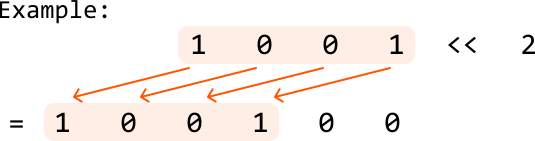
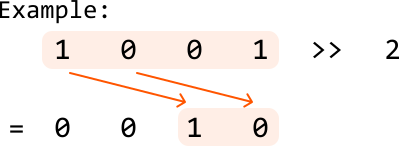
In addition, it’s also important to understand the fundamental shift operators:

Using these operators, here are some useful bit manipulation techniques to be aware of:

Real-world Example

Data transmission in networks: In many network protocols, bit manipulation is used to efficiently encode, compress, and transmit data for fast communication. For example, IP addresses and subnet masks use bitwise AND operations to determine whether two devices are on the same network. Similarly, in error detection and correction algorithms like checksums or parity bits, bit manipulation promotes data integrity during transmission by identifying and correcting errors in the binary data.
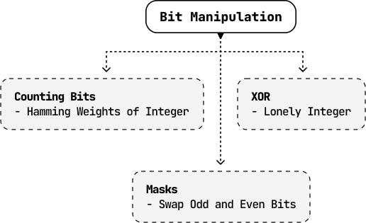
Chapter Outline

Image represents a hierarchical diagram illustrating different coding patterns within the broader category of 'Bit Manipulation'.  A rounded rectangle at the top, labeled 'Bit Manipulation', acts as the root node.  Three rectangular boxes, connected to the root node via dashed downward-pointing arrows, represent subcategories: 'Counting Bits' (containing the description '- Hamming Weights of Integer'), 'XOR' (containing '- Lonely Integer'), and 'Masks' (containing '- Swap Odd and Even Bits').  The 'Masks' box is connected to the root node by a dashed arrow, indicating a direct relationship.  The arrangement visually depicts how 'Counting Bits' and 'XOR' are distinct approaches under the umbrella of 'Bit Manipulation,' while 'Masks' is another technique, possibly building upon or related to the core concept.  The dashed lines suggest a conceptual connection rather than a strict sequential flow.

To best grasp the fundamentals of bit manipulation, this chapter explores a variety of problems that utilize a range of complex bit manipulation techniques, as well as how to identify the appropriate bitwise operator based on specific requirements.